Fight the Cheese
-
To get a
brighter
organ with even more click
and "punch",
the Miller integrator filter capacitors on all busbar summing amp
stages could be removed. This flattens the frequency response by removing
the first -6dB/Oct filter. But: It will require a modification
of the
recovery/intermediate
amplifier
as seen below,
otherwise the organ will have a too shrill and harsh sound. This is not
what you want. A little
more on the upper end is fine, but too much will sound "cheesy"
and unpleasant, too less will sound dull and boring. If you
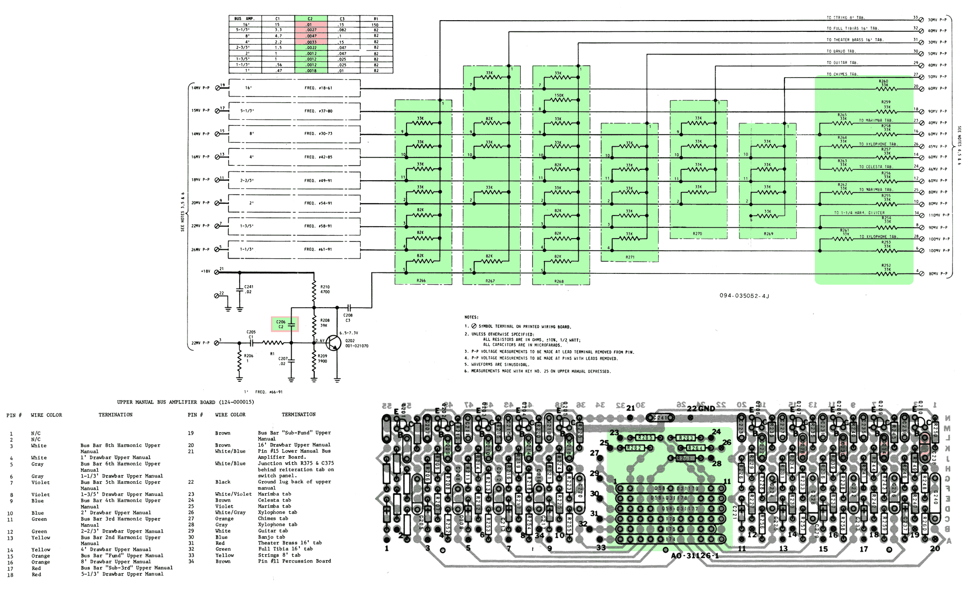
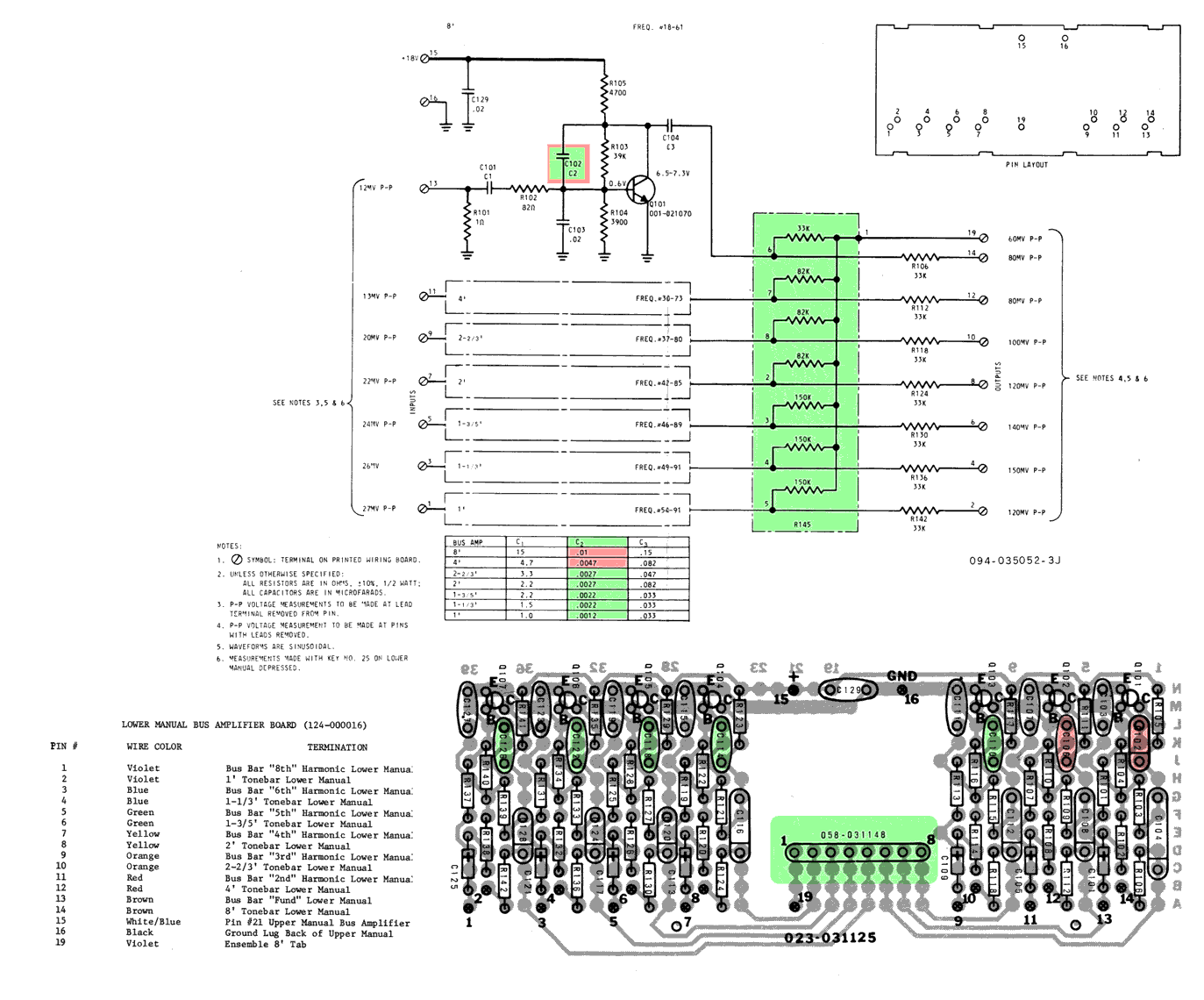
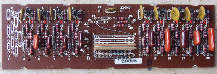
want to try it, remove all
9 Miller filter capacitors
for drawbar 1
(16') to drawbar 9 (1'). These are the parts "red X" on photo
below, numbered C238, ... also marked red and green on
upper bus amplifier
PCB layout
, same for
lower bus amplifier
PCB schematic and layout
.
.
-
Matti Kari from Finland got me aware of this problem: If you
remove all filter caps from busamps, vibrato might begin to distort in higher frequencies
when there's more than two keys pressed at the same time. Oops! I
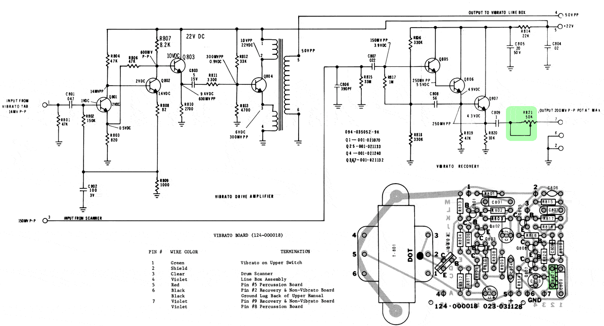
did not experience this problem, but lowering R806 on the
vibrato recovery
board
124-000018 from 47k to 33k or 22k should help. If
problem persists, raising value of R803 to 1k or 1k2 should
definitely solve the problem. Readjusting of R821 (trimpot) may be
necessary.
Bass Improvement
All upper and lower bus amplifier stages feature a
bass rolloff
to eliminate crosstalk and to remove "dirt"
from the single drawbar sound. An absolutely
great improvement
for an authentic "vintage" sound (which has all the
"dirt", i.e. bass crosstalk and noise even
on higher drawbars) could be achieved by removing
this bass rolloff. This gives a linear frequency response up
to the drawbars, like found in M3, M100 and all classic consoles,
and retains all the "dirt" we love in vintage Hammonds.
This was a great tip from Kon Zissis (Thanks, Kon!)
-
replace all capacitors in the row C240, C236,
C232... (brown/orange mylar caps) by electrolytics
10uF/40V, anode (plus) pointig to the transistors (up).
Change R247 from 150 to 82 Ohms. Replace
all electrolytics in row C237, C233, C229...by 47uF/25V
electrolytics, anode pointing up.
-
Same procedure for lower manual busamps (other item
numbers, though, but similar part locations).
Filter Flattening
Frequency response and tonal balance is essential to "the Hammond
Sound". The secret lies in a smooth low pass filtering
instead of the heavy -12dB/Oct and more for the stock T-spinetts
and by emphasising the lower midrange around 200 Hz.
The heavy filtering was done because spinets have no "
manual
tapering
" (getting a proper tonal balance through different
resistor values in the manual wiring) and key click was assumed
to be a fault in the later years. While the B-3's
AO-28
preamp
has only a slight volume
decrease to higher notes, T-Series spinetts are more radical and
cut off any higher harmonics and "noise" (i.e. click).
On the other hand, the
M-3
or
M-100
organs
are nice sounding, with a definive key click and
very
nice "bottom"
, without tapering at all. Getting
a M-100 sound out of your T-Series is pretty easy. First look
at the frequency response of the AO-29 (used in M-100 and M-3)
or Preamp, drawbar to LS output, measured in my workshop (blue
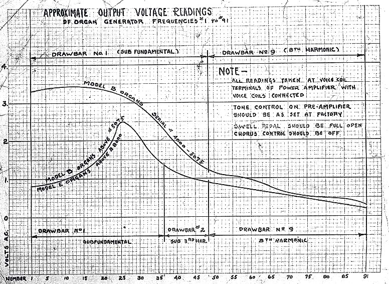
line on diagram below), or have a look on the
B-model
overall frequency response
(very "aged" diagram)
on my
tech info page
to have an idea what will sound "smooth":
:
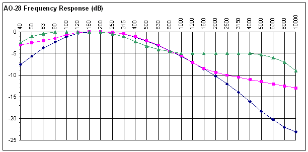
As you can see, there is an emphasis on the
lower midrange from 80 Hz to 300 Hz and a rolloff to the upper
mids. Actually, the rolloff is much less when the
amp is measured on the bench with a low-impedance audio generator
because of the matching transformer's
output impedance (see
this
Excel spreadsheet
for details), but it makes clear what we need: A filter
response that matches the AO-28 frequency response.
Filter Issues
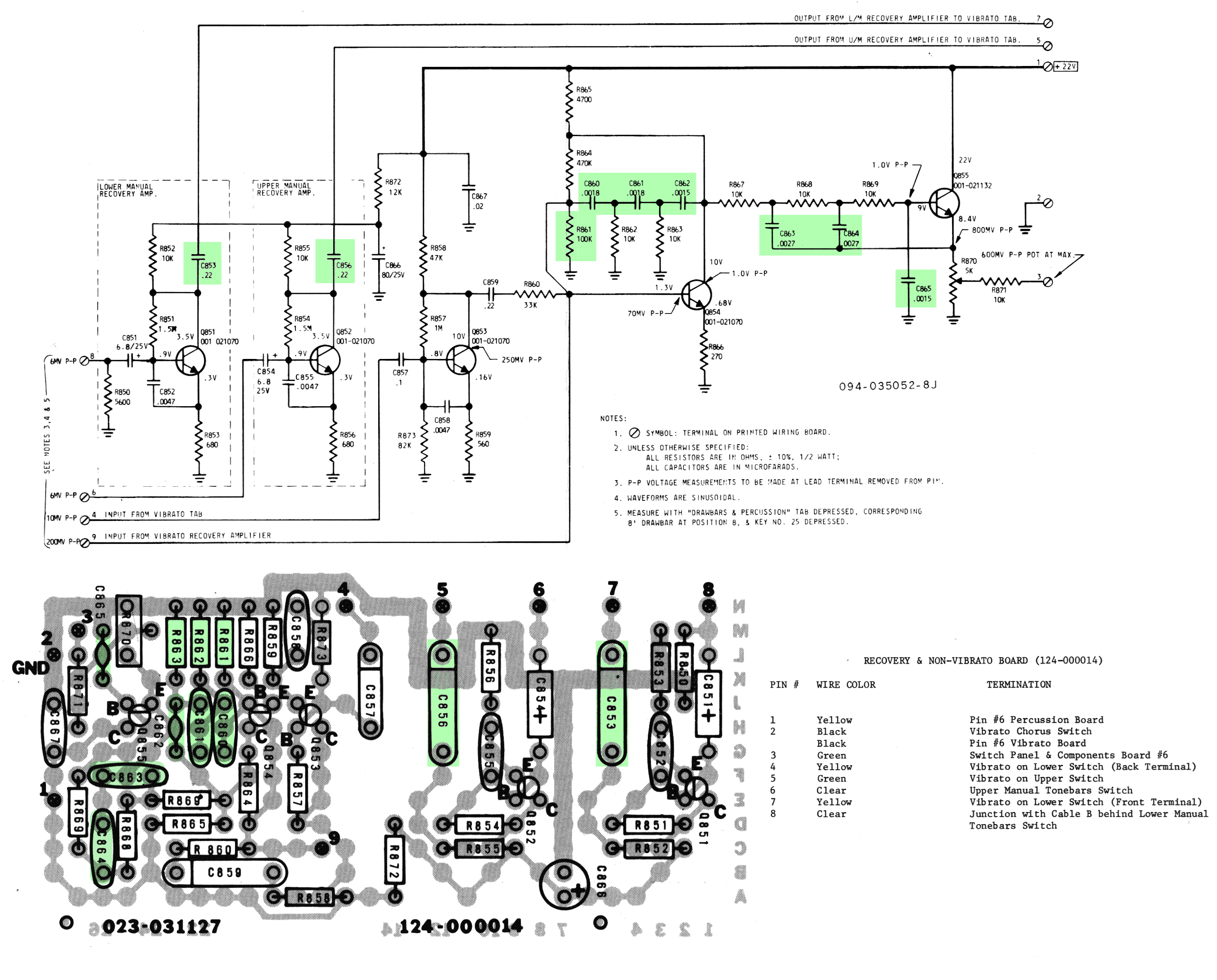
First remove the Miller integrator filter capacitors
on the bus amp
stages and remove bass rolloff, as seen above. Now
the
dreaded "click filter"
on the recovery/intermediate amp
board has to be replaced for a AO-28-like
frequency response. The recovery and intermediate amp board is
located behind the vibrato tabs
. Refer to parts marked
green
on
recovery/intermediate
amplifier PCB schematics and layout
. Print out this schematic for a better
understanding, or click pictures below to enlarge. With this
modification, you'll get a frequency response like the
violet line in the diagram above.
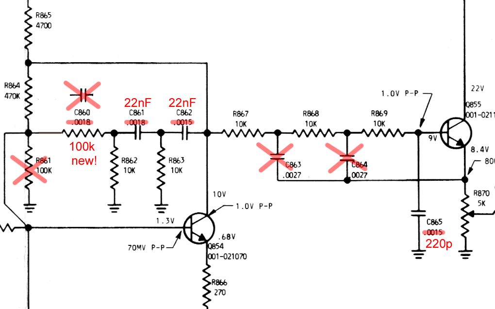
Changes to the
recovery/intermediate
amplifier
, new values in red.
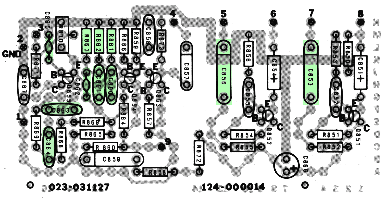
Parts to be changed on the
recovery/intermediate
amplifier PCB
are marked green.
-
Remove R861 (100 kOhms)
-
Remove C863 and C864.
-
Remove C861 and C862
and replace both with
22 nF/250V
.
-
Remove
C860. Replace with
100 kOhms
resistor
.
-
Replace C865 with
220pF
capacitor for more treble
(violet frequency response) or not (alike the blue frequency
response line).
-
For more "body" and
bass response
(the T-series sound a
little flat on the lower notes), replace the two big orange capacitors C853 and C856
(220nF) on the right side with
470nF capacitor and 4.7 kOhm
resistor in series.
-
Bridge resistor R821 (picture below, may be a fixed or a
adjustable resistor, directly connected to terminal pin 7) on the
vibrato recovery
board
(the one with the little transformer on it) with a
capacitor 1,8 nF for a better click when vibrato is ON. You may
use the obsolete C860 from above for this
.
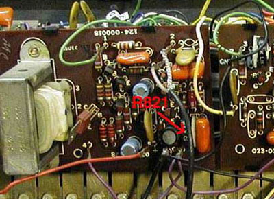
T-100 vibrato preamp board with R821
Percussion Improvement
The
multi-triggered percussion
is very annoying to the jazz
organ player. Since there are at least 3 different versions of
percussion PCBs made by Hammond, there is no simple PCB mod which
works on every spinett to get a classic
"touch response"
percussion
. Anyway, the percussion settings on some T-Series are way
too long, even if you prefer the "piinngggg"
of the M-100 (like me) over the "pip" of a B3.
-
Quick fix
for T-5xx series organs with percussion board #
124-000170
: Remove C517 (0.15 uF), replace by wire. Remove C509 (0.082 uF), replace
by wire. Remove R538 (27 KOhm). Replace R539 (1 MOhm) by 3.3 MOhm. Remove R541
(22 kOhm). Replace transistors Q512 and Q513 by PNP types (BC557 or equivalent), but:
Emitter wire in C hole, Collector wire in E hole (reverse polarity) on both.
Remove C511. Replace C510 (10 uF) with 4.7 uF (longer percussion decay) or 3.3
uF (shorter decay), rated at 35V. Works fine on all my T-500 mods. Background:
This converts the busbar transient amplifier into a emitter
follower which just responds to the first pressed key.
-
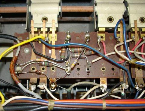
Quick fix
for T-100/200 series organs with thyristor percussion board
(commonly used on these organs): Remove brown 0.082
uF capacitor next to red wire from board, solder a 0.022
uF capacitor to the back side exactly as shown
(see photo).
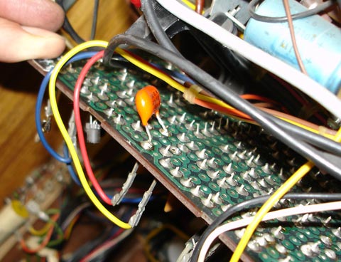
-
When you're at it,
shorten percussion length
by
replacing 1 MOhm resistor located at "Reiteration"
switch by 330 kOhm (or solder in parallel) for a shorter
"fast" percussion setting and 3.3 MOhm by
820 kOhm for a shorter "long" percussion setting
(T-100 and T-200 only).
-
OR
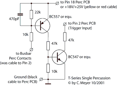
, if you have a different percussion board: Add a
transistor circuit
that eliminates multi-triggering percussion. This
little circuit has to be inserted between the white or white/red cable from the
percussion busbar to pin 15 (some early organs on pin 2, see organ schematics)
of the percussion PCB. Needs +Ub supply from percussion board (yellow or red cable,
check with voltmeter). May be build on a breadboard. Again a hint from
Matti: On some percussion boards, the pin numbers are not the same than in here.
+22V is available on pin 5/6 or 16/17 on early organs (refer to organ
schematics). Ground is easiest obtained from pin 1. The diagram states pin 2 as
percussion rail input, but should read as pin 15 in most cases as mentioned
above.
Now play your organ. Pretty well, is'nt it? But hey -- the
percussion voices
still suck
. "Celesta" is usable, but
"Geeetar"?
So proceed to
Skill 3
.
|